Corne keyboard building
Table of Contents
The Corne kit
Initial build
The kit that I purchased on Shopee
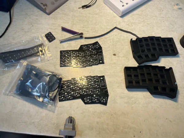
The kit content:
- Some PCB
- Some microcontrollers and OLED screen
- Some sockets
- Some SMD diode
Diodes and sockets
Those components are soldered on the backside of the PCBs
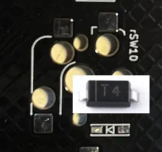
To solder the SMD diode, apply some solder to the conductive pad on the PCB first, then place the diode on the pad, in the correct orientation. In my case, the Cathode is marked with a small line, so we align it with the line on the silk screen. Use a tweezer to position it, then use the soldering iron to heat up each end of the diode.
Then we solder the sockets. The socket is rather easy to solder, as it stays in place very neatly. Put your soldering iron near the terminals of the socket, feed solder in liberally. If the joint is hot enough, the solder will distribute evenly due to surface tention.
![[socket-solder-joint.jpg|340x453]]
The most tedious part of the solder is now done
Power switch, buttons and sockets
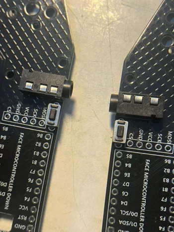
First we solder the two TRRS sockets, for wired connectivity, and the two reset buttons. Remember to place them on the front side of the PCB (the opposite side of the previous step)
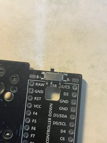
Next, we solder the power switch. This is to allow me turning off the keyboard. The switch is also SMD, so I find it easier to get good solder joints by applying a very tiny amount of solder on each solder pad, and then heat each of them up
Then the microcontroller sockets. I find it helpful to use some electrical/heat resistant tape to secure the socket in place before flipping it over for soldering
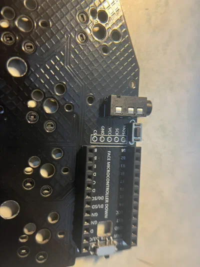
The socket for the OLED display, on my board, has a little bit of mismatch. There are 5 soldering holes, but I was provided with just a 4-socket rail. I made sure that the rails is installed on top of the GND, VCC, SCK and MOSI socket. It is also a good idea to keep the socket in place by taping it
Microcontroller
To solder the connectors onto the microcontrollers, I first measured and cut out the two pin rails, then put them on a breadboard to secure them
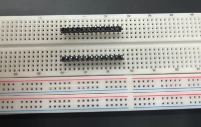
Then put the microcontroller on top of the pin. For the Corne, the microcontroller should be top down.
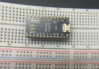
A tip for a nice rail soldering: I solder both end first to make sure the rail sit flush on top of the board. If you go solder every joints sequentially, the rail may lift a bit above the board
Microcontroller height profile
After installation, I found out that the standoff 💭 💭 The little copper, hexagonal things that is a little bit tall and can be used to screw stuffs in between the seller gave me cannot clear the height of the whole PCB + MCU complex. Even if I replace the standoff to something taller, it wouldn’t look okay. So I have to set out and fix the whole thing
On the default design, there would be quite a big gap between the PCB and the MCU. This is good if you want to put a little battery underneath them, like this:
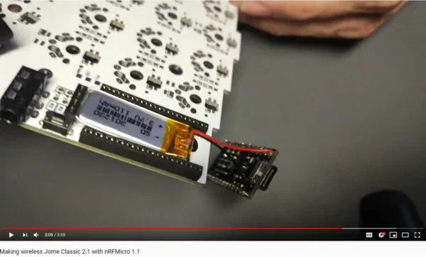
Also to make this as neat as possible, the socket they used are just 3.5mm high and they solder the PLS pin in reverse on the MCU. See: GitHub: joric/nrfmicro.
Because I’m not putting a small battery underneath the MCU but under the PCB instead, the whole thing has an annoying empty space underneath: 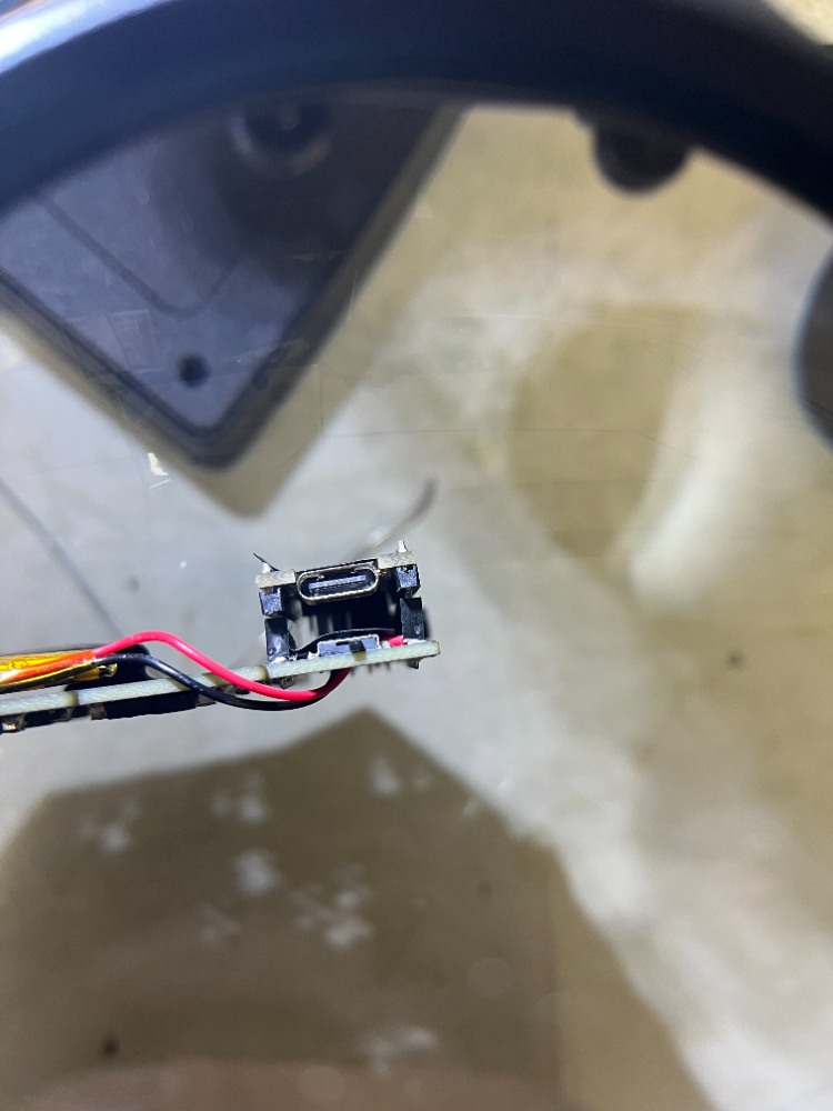
Does this matter? Yes. Because when I put this PCB in the case, with the OLED installed, the 3D printed OLED cover doesn’t fit 💭 💭 I could have find some taller copper standoff for this, but in the end it will still looks ugly : 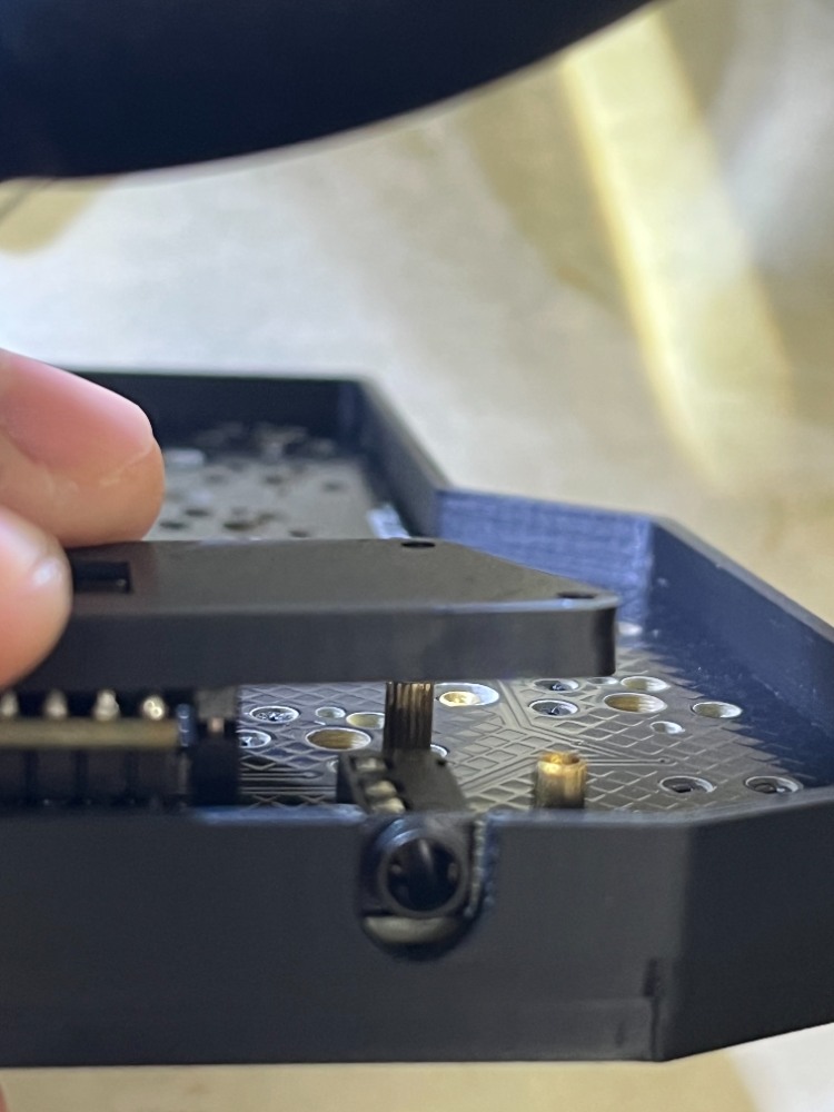
The aesthetically better way for me to make the MCU hotswappable is using the Machine Pin Socket. This socket is more available for me to purchase. The pins to be soldered on the MCU is harvested from 2.0mm pin rails 💭 💭 This is a smaller variant, for using with LED strips. Normal PLS pins rails are spaced 2.54mm apart
Having soldered all the default stuffs in the kit, I have to desolder the MCUs, the sockets and start again. Unluckily, the MCUs didn’t survive the whole ordeal. In short, after desoldering the rails I got 2 broken ProMicro on my hand that I need replacing. The two keyboard PCBs seem to have also burnt the insulating layer on top from too much desoldering.
I follow the approach outlined in this video to solder the pins to the MCUs
I would say that experimenting on electronic can be really frustrating and time consuming, very unlike fiddling with software. A bit of careless soldering means either you have to spend 30 minutes desoldering everything to try again. So you should really plan out and carefully check all the parameters before going forward with solidifying everything with a soldering iron
Final assembly
Thank god the PCBs haven’t broken after such intensive soldering/desoldering Overall the only thing I need to replace was the ProMicro MCUs. I’d blame the seller a little for not giving me the correct instruction.
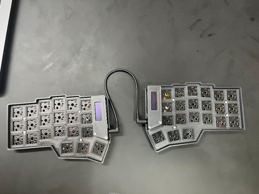
Setting it up
Flashing the firmware
The process is really simple. We will flash into each side of the keyboard. Do not connect them together during this process.
I got a customized keymap from
https://nickcoutsos.github.io/keymap-editor/. After letting it build using Github action, I got 2 firmware files corne_left_studio.uf2 and corne_right_studio.uf2.
To flash the firmware into my keyboard
- I plug the keyboard side into my Mac.
- I hold the reset button for 3 seconds, release, and press once more.
- The MCU showed up as another disk drive on my Mac. I paste the respective UF2 file into the drive, and after a few seconds the MCU auto ejected.
Do that for the respective other side and everything is done.
The key switch shenannigan
When I bought this kit, I specificly choose a PCB for low-profile switches. Then I proceed to buy some low profile switches on the internet. Color me surprised when the switches I bought doesn’t fit the socket.
Unlike normal profile switches, which mostly follows the Cherry MX standard footprint, there are no standard pin layout for the low-profile switches. The most common ones are Kailh Choc, but even them have 2 versions.
The switches I bought was Kailh v2. The PCB is for Kailh v1.
To make the matter worse, Kailh v1 only supports the 2-stemmed keycaps format
💭
💭
I found some literature referring to this type of keycap as MBK
. I bought a set of keycap with the standard plus-sign stem.
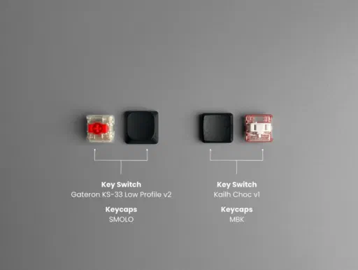
So, a good advice is to always do your research properly and buy the correct switches & keycap for your need, especially with low-profile keyboard
Final product
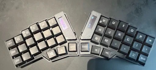
I ordered some keyboard sticker online, and put them to help me remember which key is what.